- Sets
Astable Multivibrator
let it blink
Michael Knieling
English
Advanced
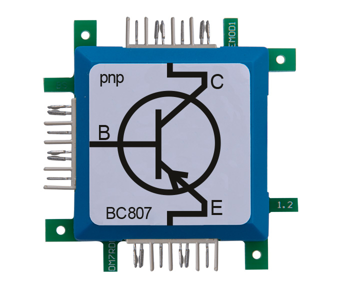
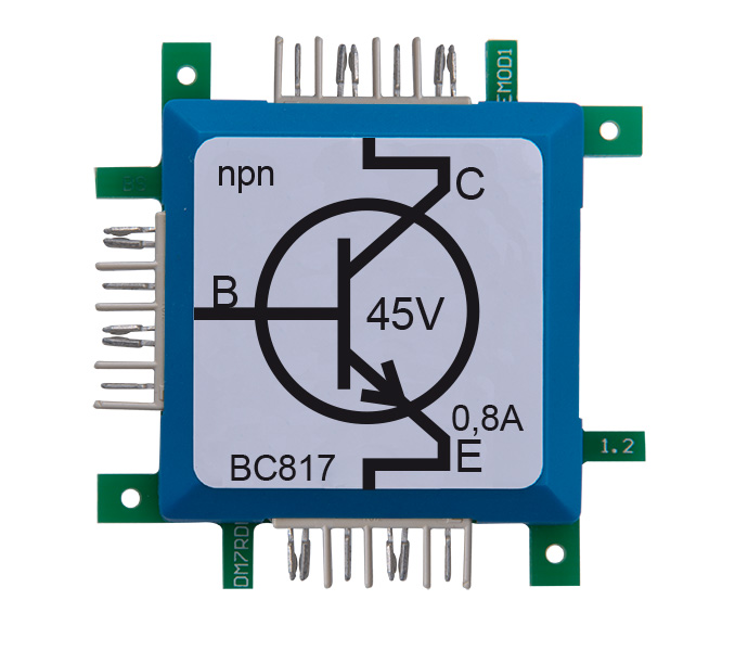
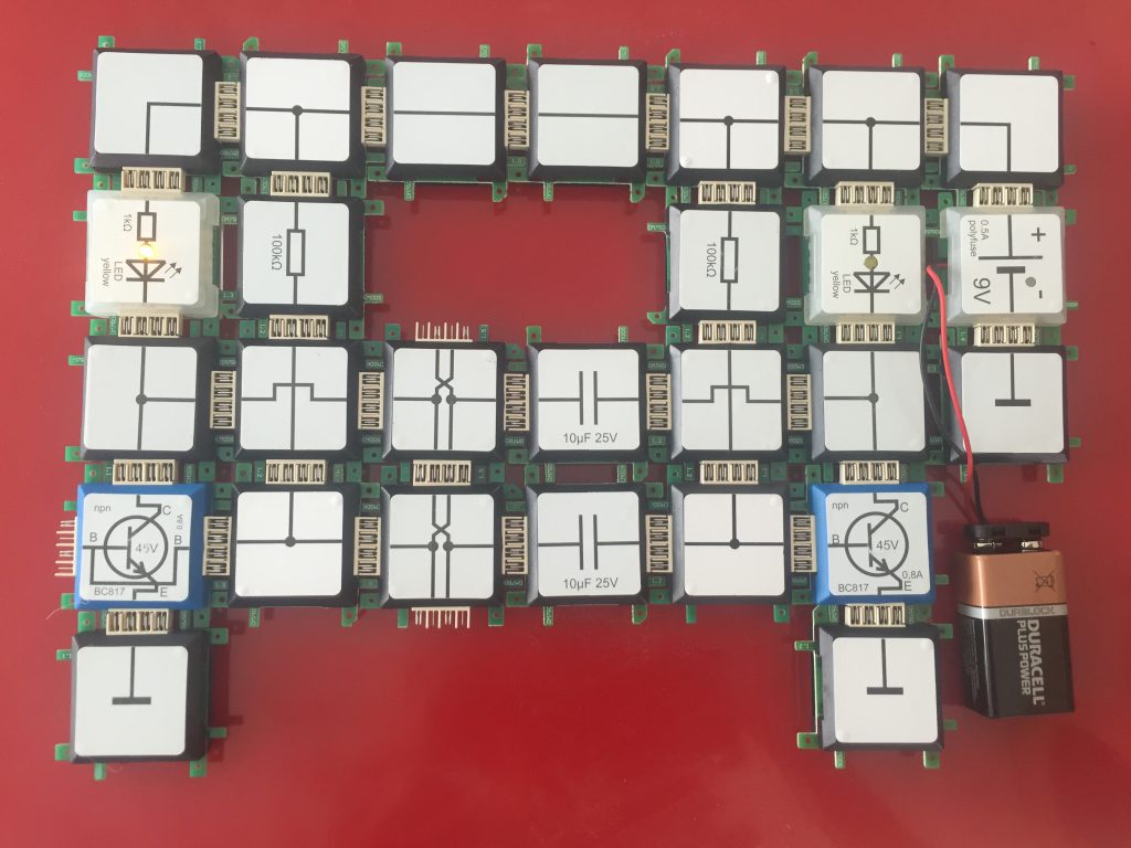
A classic circuit for generating a square wave oscillation. Two transistors are used in the circuit with always one in on and the other in off condition. Two capacitors and two resistors are used to dene the total cycle of the oscillation. The transistors are used for charging and discharging the capacitors. This type of circuit is called astable multivibrator, in our circuit the astable operation is shown by the blinking LEDs, when the frequency is low enough. The period can be roughly calculated: T= 2 In(2) R C = 2 In(2) 100kΩ 10µF = 1.39s The Advanced set includes capacitor- and resistor-bricks with different values. In this example the value of the bricks can be changed to manipulate the frequency. The left resistor and the upper capacitor control the switching behavior of the left transistor and reverse. If the resistor and capacitor are not equal at both sides, an asymmetric pulse duration is achieved. It is not possible to allow the circuit to remain in a stable state, that´s why its also called astable.


